Overview
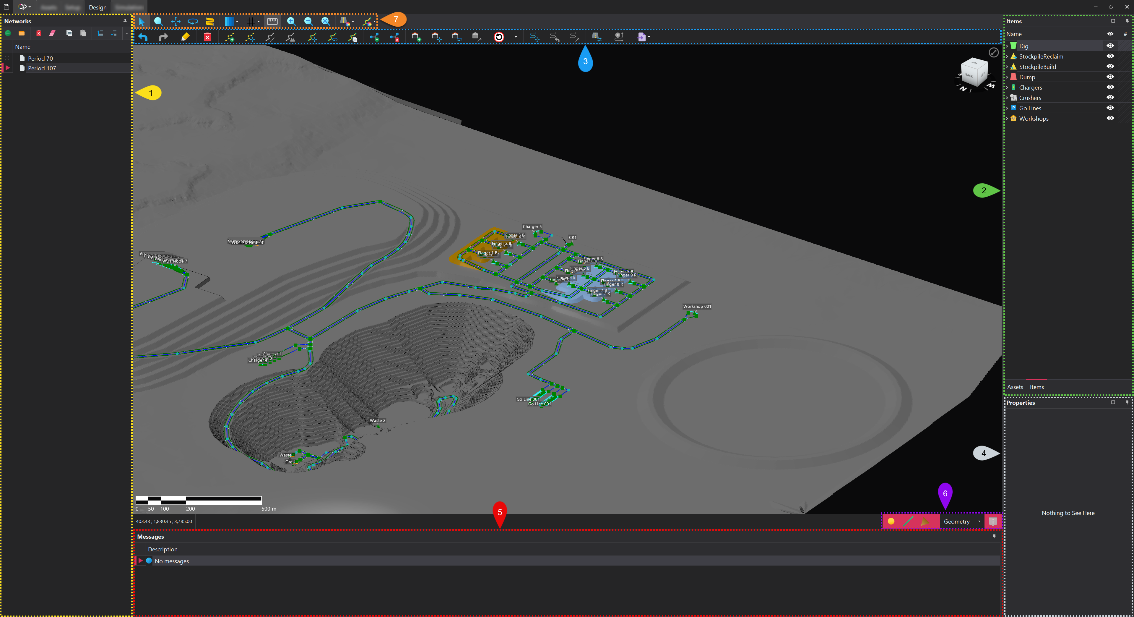
The Design tab features several key components, each numbered on the image below. Each number on the image corresponds to the detailed description provided in this page, illustrating the function and purpose of each component.
📖 For a more comprehensive understanding, it is recommended to review the Network Basics page before proceeding, as it provides essential context on the components discussed in this page.
1. Networks
The Networks panel is used to store Networks which are the haul road layout for a particular state of the mine (e.g., the face position in year one and the face position in year two). Each Network created, will have its own associated haul road layout, allowing for different configurations of haul roads to exist for the same state of the mine. When setting up simulation runs, each simulation must have one of the specified Networks must be selected.
Networks can be managed and organised through the toolbar at the top of the panel. More information on the functions within the toolbar can be found in the Common User Controls page.
🗂️ To help with organisation, networks can be nested within folders, making it easier to categorise different configurations.
2. Assets & Items
Assets
This tab displays the Assets that have been loaded into the project. The organisation and strucutre of the assets mirrors that of the actual Assets tab. In addition to the name column, which is populated based on the structure, there are two additional columns:
| Column | Description |
|---|---|
| Visiblity | Featuring an eye icon, this icon controls the visibility of the asset in the viewport. If the Asset is in the hidden state, the icon will have a diagonal line through it. |
| Display Settings | The look and feel of the asset shown in the viewport. More information on Asset display settings can be found here |
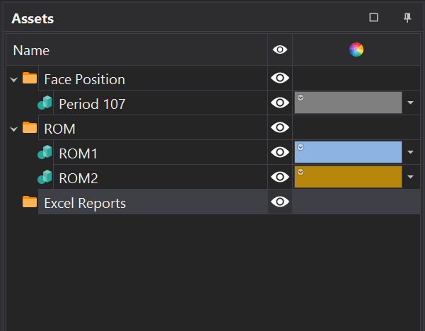
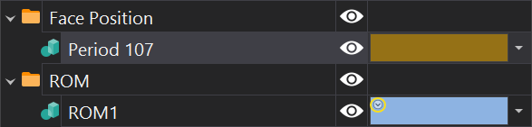
🔍 If an Asset's appearance has been overridden, you will not see the little circle with a downward arrow head in the top left corner of the color box.'.
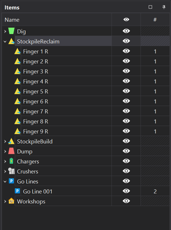
Items
This tab, displays the entities from the Items step, as well as the Sources and Destinations step.
Each entity is nested under its respective parent container. Alongside the name column, there are two additional columns.
| Column | Description |
|---|---|
| Visiblity | Featuring an eye icon, this icon controls the visibility of the item in the viewport. If the item is in the hidden state, the icon will have a diagonal line through it. |
| Count | Indicates how many instances of the Item are present in the current network. In most cases this will be 1; however, Fixed items, such as Go-Lines, can have multiple instances. |
3. Design Toolbar
The design toolbar offers a range of tools for creating haul networks. It is divided into partitions, each dedicated to specific functions, providing an organised approach to network design.
| Tool | Description |
|---|---|
Undo/Redo  | Enables reversing or reapplying changes made to the design, offering flexibility and error correction during editing. Ctrl+Z can also be used for undo, and Ctrl+Y for redo. |
Draw  | Enables the creation of network paths by drawing Edges. |
Delete  | Enables the deletion of Points, Edges and Terminals. |
Point Edit  | These tools enable control over Point placement and adjustment within the network design. 1️⃣ Add Point to Edge 2️⃣ Move Points (F) 3️⃣ Apply Gradients Between Points 4️⃣ Drape Points Onto Surfaces |
Edge Edit  | These tools enable control over Edge placement and adjustment within the network design. 1️⃣ Move Edges (CTRL-F) 2️⃣ Rotate Edges 3️⃣ Copy Edges |
Intersection Edit  | Enables the creation and deletion of manual Intersections. 1️⃣ Add Intersections 2️⃣ Remove Intersections |
Terminal Edit  | These tools enable control over Terminal placement and adjustment within the network design. 1️⃣ Add Terminal Location 2️⃣ Move Terminal Location (F) 3️⃣ Rotate Terminal Location 4️⃣ Rotate and Connect Terminal To Point |
Signs  | Enables a Speed Sign to be selected and then applied to relevant Arcs in the network. Stop signs can also be selected and placed a intersections within the network. |
Road Smoothing  | These tools enable functionality over the smoothness of Edges. 1️⃣ Move Control Points (SHIFT-F) 2️⃣ Reset Control Points 3️⃣ Auto Smooth Control Points |
Reverse Lanes  | Reverses the direction of the selected Lane. Only relevant for single lane roads. |
Show Path Between Terminals  | Highlights the path between two selected Terminals. |
Import Network  | Enables the import of network data from third-party applications. Currently, only the Alastri Haul Infinity Segments CSV format is supported. |
4. Properties Panel
The properties panel displays the attributes of the currently selected items—Points, Edges, Terminals, and Intersections.
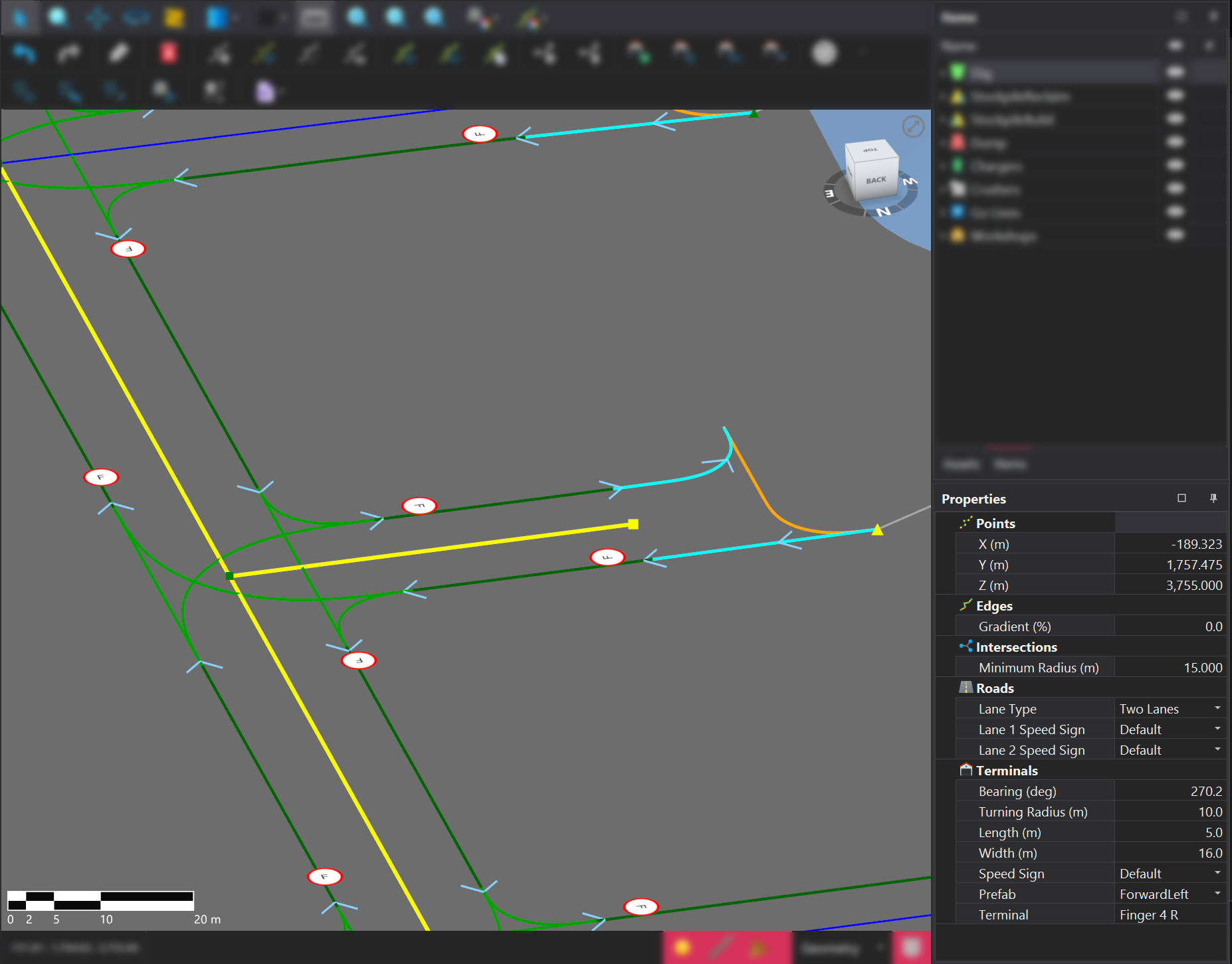
The table below outlines the properties and their corresponding descriptions.
| Property | Entity | Description | Editable |
|---|---|---|---|
| X | Points | The X-coordinate of the point. | True ✅ |
| Y | Points | The Y-coordinate of the point. | True ✅ |
| Z | Points | The Z-coordinate of the point. | True ✅ |
| Gradient | Edges | The gradient of the selected edge(s). | False ❌ |
| Lane Type | Roads | The current lane type applied to selected arcs. | True ✅ |
| Lane Speed Sign | Roads | The current speed signs applied to lane instances. | True ✅ |
| Minimum Radius | Intersections | The minimum radius of the intersection or terminal. | True ✅ |
| Terminal Configuration | Terminals | Detailed settings for the current terminal. For full details, refer to the Terminal Configuration Documentation. | True ✅ |
📋 Any changes made to property values will automatically apply the updates to all selected items, ensuring consistency across the selection. This feature allows for efficient bulk modifications, saving time and reducing the need for repetitive adjustments..
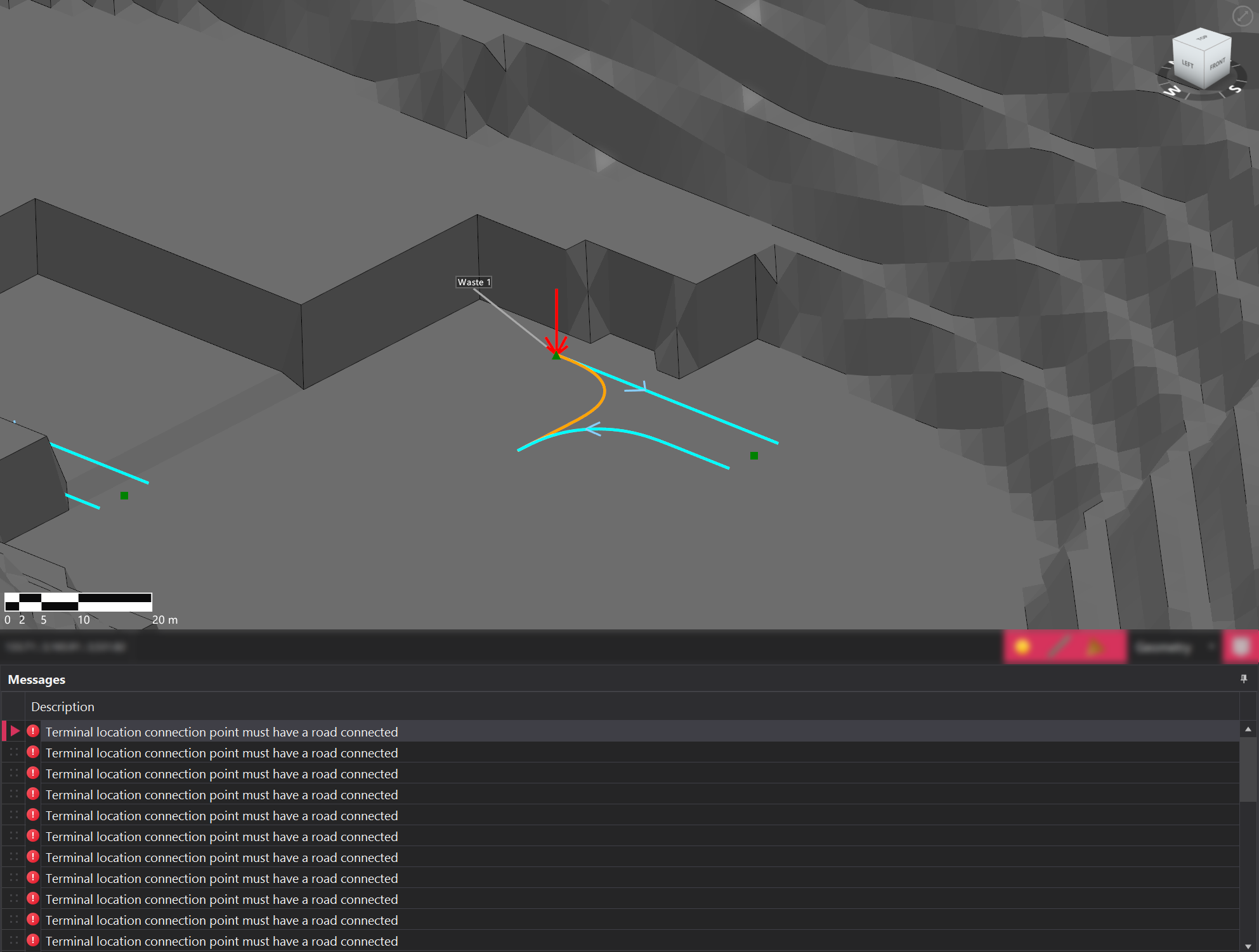
5. Messages
The Messages panel displays any warnings or errors related to the currently selected network. Failure to resolve errors may prevent simulation runs from starting.
🖱️Clicking on an error message will automatically focus the camera on the specific item where the issue is occurring, enabling faster identification and resolution of problem areas within the network. This feature streamlines troubleshooting by guiding the view directly to the source of each error.
6. Snapping Mode
There are several snapping modes that can be used in the Design tab, each of which has has configurable properties.
| Mode | Description |
|---|---|
| Geometry | Allows for snapping to triangles, lines, and points, with each option easily toggled on or off by selecting the corresponding button. |
| Z-Plane | Sllows for snapping to defined Z RL. The RL can be specified in the input box that appears when this mode is enabled. |
| Gradient | Enables point placement such that the resulting edge follows a predetermined gradient. This mode requires a point to be drawn first before it can be activated |
⌨️ Pressing the S key switches the snapping mode, allowing for faster and more efficient network design.
7. Viewport Toolbar
In addition to the tools found in the common viewport toolbar, two additional tools can be found.
| Tool | Description |
|---|---|
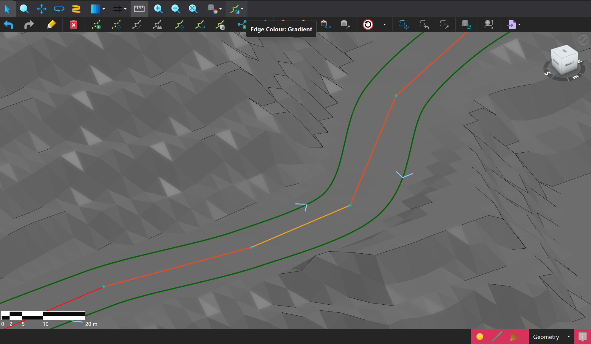
Lane Shading  | Configures the lanes to be shaded based on Type (default), Speed, or Gradient. |
Edge Shading  | Configures the edges to be shaded according to their default color or Gradient. |